Building and Powering AAR A Trucks: Difference between revisions
| (26 intermediate revisions by the same user not shown) | |||
| Line 7: | Line 7: | ||
5 March 2015 | 5 March 2015 | ||
[[File:2015-02-28 21.35.12.jpg|thumb|right|400px|AAR Type A truck, partially completed. Two motorized wheelsets shown the background.]] | [[File:2015-02-28 21.35.12.jpg|thumb|right|400px|AAR Type A truck, partially completed. Two more motorized wheelsets are shown in the background.]] | ||
A little over 12 years ago I purchased a set of castings from [[MDM Locomotive Works]] to build a pair of AAR A trucks. I am really impressed with this kit, as it includes everything except the motors. It includes all screws and hardware, flame cut parts for brakes, wheels, axle material, even a set of [http://www.clippard.com/ Clippard] air brake cylinders. It's really a shame that no one has taken over [[Jim Murray|Jim Murray's]] fine business. | A little over 12 years ago I purchased a set of castings from [[MDM Locomotive Works]] to build a pair of AAR A trucks. I am really impressed with this kit, as it includes everything except the motors. It includes all screws and hardware, flame cut parts for brakes, wheels, axle material, even a set of [http://www.clippard.com/ Clippard] air brake cylinders. It's really a shame that no one has taken over [[Jim Murray|Jim Murray's]] fine business. | ||
I have worked on this kit off and on since I purchased it. I | I have worked on this kit off and on since I purchased it. I was never quite sure how to power the trucks. I wanted electric driven axles, as I know how to design and wire the electric circuits. Recently (well, about a year ago), I decided to put more effort into constructing the trucks, partially in hopes that an epiphany would come regarding what motors to use and how to mount them. | ||
This plan has worked. I am nearing | This plan has worked. I am nearing completion of the trucks, including the electric motor drives. The motor design is simple but effective, and may be used on other truck styles or even single axle trucks, such as on Plymouth switchers. This article will illustrate the method and materials I used. | ||
== AAR A Trucks == | == AAR A Trucks == | ||
| Line 26: | Line 26: | ||
== Electric Motor == | == Electric Motor == | ||
[[File:MY1016 Dimensions.jpg|thumb|right|300px|MY-1016 Electric Motor dimensions, numbers in parenthesis are inches, all others are millimeters]] | |||
I finally settled on an electric motor for the trucks. I chose the MY-1016 scooter motor, which is commonly available on eBay and other scooter supply sites on the Internet. The motor has a convenient four-bolt motor mount and includes an 11-tooth sprocket for #25 chain. It is rated at 24 volts D.C. with maximum power consumption of 250 watts (about 1/3 horsepower). The best part is that the motor is very affordable. They can be had for less than $40 each. | I finally settled on an electric motor for the trucks. I chose the MY-1016 scooter motor, which is commonly available on eBay and other scooter supply sites on the Internet. The motor has a convenient four-bolt motor mount and includes an 11-tooth sprocket for #25 chain. It is rated at 24 volts D.C. with maximum power consumption of 250 watts (about 1/3 horsepower). The best part is that the motor is very affordable. They can be had for less than $40 each. | ||
| Line 31: | Line 32: | ||
A single MY-1016 motor drives my mini-F9 diesel, which has plenty of power for hauling. I believe that four of these motors, one per axle, will provide more than enough pulling power for my target diesel. | A single MY-1016 motor drives my mini-F9 diesel, which has plenty of power for hauling. I believe that four of these motors, one per axle, will provide more than enough pulling power for my target diesel. | ||
Specifications: | |||
* Voltage: 24Vdc | |||
* Rated Speed: 2650-2900 Rpm | |||
* Rated Current: 16.0-16.4A | |||
* Output: 300 Watt | |||
* Sprocket: Removable Bolt Sprocket | |||
* Case Length: 4-1/8" (105 mm) | |||
* Case Diameter: 3-15/16" (100 mm) | |||
* Drive Shaft Length: 1" (25 mm) | |||
* Drive Shaft Diameter: 5/16" (8 mm) | |||
* Bolt Hole Distance (Adjacent): 4-1/8" (105 mm) | |||
* Bolt Hole Distance (Cross Bracket): 2-3/16" (56 mm) | |||
* Motor rotation when red lead is positive: clockwise | |||
Notes: | |||
1. There are different versions of the MY1016, each with a different power rating and slightly different size. There is a 350 watt version with a slightly longer body. | |||
2. The mounting holes are threaded for metric bolts. If you'd rather use English bolts you can chase the threads with a 1/4-20 tap. Be sure to use plenty of cutting oil. | |||
== Bill of Materials == | == Bill of Materials == | ||
This section provides a list of materials used for mounting the motor to the axles | This section provides a list of materials used for mounting the motor to the axles and for the chain drive system. | ||
Each wheel set (pair of wheels and an axle) | Each wheel set (pair of wheels and an axle) use the following components. The quantities required are shown in parenthesis. | ||
* (1) Electric Motor - MY-1016 | * (1) Electric Motor - MY-1016 | ||
| Line 65: | Line 85: | ||
The only custom | The only custom parts in the list above are the "Motor mount bushing" and the "Tee brace". I turned the bushings out of 3/4 inch round bar [[CRS]]. They help stabilize the pillow blocks and provide a solid foundation for the heads of the bolts securing the motor to the pillow block. | ||
The "Tee brace" parts are modified stock Tee braces used in building construction. They prevent the motor from spinning on the axle. | |||
I ordered the large sprockets directly from Martin Sprocket. They came with a 1/2 inch bore and no key or set screw. The MDM truck kit came with 1/2 inch axle stock, but I prefer 3/4 inch and substituted using 3/4 inch round [[CRS]]. The sprockets were drilled and bored from 1/2 inch to 3/4 inch, then placed on the axles in the correct location and [[Taper pin|taper drilled]] all the way through. The sprocket was locked into place by driving the taper pin and cutting off the excess. | I ordered the large sprockets directly from Martin Sprocket. They came with a 1/2 inch bore and no key or set screw. The MDM truck kit came with 1/2 inch axle stock, but I prefer 3/4 inch and substituted using 3/4 inch round [[CRS]]. The sprockets were drilled and bored from 1/2 inch to 3/4 inch, then placed on the axles in the correct location and [[Taper pin|taper drilled]] all the way through. The sprocket was locked into place by driving the taper pin and cutting off the excess. | ||
| Line 74: | Line 96: | ||
File:2015-03-06 12.28.45.jpg|T Plate 5x5 inches, unmodified | File:2015-03-06 12.28.45.jpg|T Plate 5x5 inches, unmodified | ||
File:T Plate 5x5.jpg|5x5 inch T Plate modifications | File:T Plate 5x5.jpg|5x5 inch T Plate modifications | ||
File:AAR A Modified Tee Brace DNevil.jpg|Here is a Tee Brace after drilling the extra holes, trimming the arms and painting. | |||
File:2015-03-06 12.31.18.jpg|Everbuilt #304 1/2 inch pipe U-bolt | File:2015-03-06 12.31.18.jpg|Everbuilt #304 1/2 inch pipe U-bolt | ||
File:Bushing AARA DNevil 20150101.png|Motor mount bushing | File:Bushing AARA DNevil 20150101.png|Motor mount bushing | ||
| Line 82: | Line 105: | ||
<gallery widths="300px" heights="300px"> | <gallery widths="300px" heights="300px"> | ||
File:Drilling Tapered Whole AAR A Truck Sproket.jpg|Drilling a | File:Drilling Tapered Whole AAR A Truck Sproket.jpg|Drilling a hole through the sprocket and axle. The hole will be tapered with a reamer. Be sure to use lots of lubricant to keep the bit cool. Make sure the hub of the sprocket is facing towards the short end of the axle. | ||
File:Reaming Tapered Hole AAR A.jpg|Reaming a tapered hole after drilling. Rapid Tap works well to keep the reamer cool. Pull the reamer out frequently to extract chips, then apply more cutting fluid. | File:Reaming Tapered Hole AAR A.jpg|Reaming a tapered hole after drilling. Rapid Tap works well to keep the reamer cool. Pull the reamer out frequently to extract chips, then apply more cutting fluid. | ||
File:Chain Sprocket Axle Tapered Pin AAR A.jpg|A completed axle with the #25 chain drive sprocket attached with a tapered pin. The pin has been lightly driven in with a chisel and hammer, and the extra length cut off neatly. | File:Chain Sprocket Axle Tapered Pin AAR A.jpg|A completed axle with the #25 chain drive sprocket attached with a tapered pin. The pin has been lightly driven in with a chisel and hammer, and the extra length cut off neatly. | ||
File:Assembling Drive Chaing AAR A Wheelset.jpg|Assembling the #25 chain on the sprocket and motor. This step is performed after attaching the motor to the | File:AAR A Motor Mount Assembly DNevil.jpg|The pillow blocks are slid onto the axles. Make sure both Zerk fittings point the same way. Assemble the motor onto the pillow bearing using the motor mount bushings and a bolt, both inserted from the underside of the pillow block towards the motor. | ||
File:Assembling Drive Chaing AAR A Wheelset.jpg|Assembling the #25 chain on the sprocket and motor. This step is performed after attaching the motor to the pillow blocks using four motor mount bushings and four M6-1.00 x 40 hex cap bolts. | |||
File:Marking chain link AAR A.jpg|Place the chain on the two sprockets in order to measure the correct length. You will need to use either a Connecting Link or Offset Link, depending on which section of the chain must be removed. Use a black Sharpie marker to indicate which link pins to remove. | File:Marking chain link AAR A.jpg|Place the chain on the two sprockets in order to measure the correct length. You will need to use either a Connecting Link or Offset Link, depending on which section of the chain must be removed. Use a black Sharpie marker to indicate which link pins to remove. | ||
File:UsingChainBreaker.png|Use a Chain Breaker to remove the unwanted link. Refer to the video [https://www.youtube.com/watch?v=KJa7eVGriho Splitting a Chain with a Chain Breaker] | File:UsingChainBreaker.png|Use a Chain Breaker to remove the unwanted link. Refer to the video [https://www.youtube.com/watch?v=KJa7eVGriho Splitting a Chain with a Chain Breaker] | ||
File:Chain attached With link.jpg|The chain is attached with a Connecting Link in this case. | File:Chain attached With link.jpg|The chain is attached with a Connecting Link in this case. | ||
File:Completed Motor Sprocket Bearing Set.jpg|A completed drive chain, waiting for wheels to be pressed on. Note that the Zerk fittings on the bearings are both on the same side. | File:Completed Motor Sprocket Bearing Set.jpg|A completed drive chain, waiting for wheels to be pressed on. Note that the Zerk fittings on the bearings are both on the same side. | ||
File:Zerk protector on bearing block AAR A.jpg|The Zerk fittings on the | File:AAR A Motor Washer Spaces DNevil.jpg|Washers may be inserted between the motor and pillow block to remove slack in the chain. | ||
File:Bearing Block set screw AAR A.jpg|These | File:Zerk protector on bearing block AAR A.jpg|The Zerk fittings on the pillow block were protected by a plastic cap. The Zerk is unscrewed in order to remove the cap. Be sure to tighten the Zerk fitting back in place. | ||
File:Bearing Block set screw AAR A.jpg|These pillow blocks were selected because they include set screws that prevent the blocks from sliding laterally on the axle. This photo shows one of the set screws. Make sure the chain is aligned between the motor sprocket and the axle sprocket, then tighten the Allen set screws on both bearings. Note that there are two set screws per bearing. Also note that the set screws are on the opposite side from the sprockets. | |||
File:Completed Wheelset AAR A.jpg|A completed wheelset after pressing on the wheels. The wheelset is ready to be mounted into the truck frame. | File:Completed Wheelset AAR A.jpg|A completed wheelset after pressing on the wheels. The wheelset is ready to be mounted into the truck frame. | ||
File:Test fitting t bracket ubolt AAR A.jpg|Test fitting the T-brace along with the U-bolt before cutting the extra length off the T-brace. The motor T-brace is attached to the motor block | File:Test fitting t bracket ubolt AAR A.jpg|Test fitting the T-brace along with the U-bolt before cutting the extra length off the T-brace. The motor T-brace is attached to the motor pillow block using two nylon lock nuts. Likewise the U-bolt nuts are replaced with nylon lock nuts. This allows the tension on the rubber hose to be adjusted. The U-bolt/rubber tube configuration allows the motor to rotate on the axis as the wheelset moves up and down over the road. | ||
File:AAR A Truck Motor Mount to Frame.jpg|The motor is secured to the outside frame using the modified Tee brace along with the UBolt and a section of rubber tubing. The combination allows the motor to move up and down with the shifting height of the axle. The flat bracket supplied with the UBolt is added on top of the Tee brace for added strength. | |||
</gallery> | </gallery> | ||
== Wiring == | |||
The factory connectors were cut off from the feed wires to the motor. Standard fork terminals were crimped onto the ends of the wires. | |||
Note that the motors are facing opposite directions (see Photo 1). This will require swapping the leads on one of the motors so that the wheels will turn in the same direction. | |||
== External Links == | == External Links == | ||
* [http://en.wikipedia.org/wiki/AAR_type_A_switcher_truck AAR Type A Switcher Truck] | * [http://en.wikipedia.org/wiki/AAR_type_A_switcher_truck AAR Type A Switcher Truck] | ||
* [http://www.mdmlocomotiveworks.com/PAGES/switcher.htm AAR Type A Truck, <i> | * [https://web.archive.org/web/20130815055902/http://www.mdmlocomotiveworks.com/PAGES/switcher.htm AAR Type A Truck, <i>Archive.org</i>] | ||
* [http://nevil.org/files/live_steam/2137074_RAILWAY_CAB_TRUCK.pdf "Railway Cab Truck", U.S. Patent 2,137,704] | * [http://nevil.org/files/live_steam/2137074_RAILWAY_CAB_TRUCK.pdf "Railway Cab Truck", U.S. Patent 2,137,704] | ||
* [http://www.agrifeedonlineexpo.com/slinkimages/4/roller_chain_instalation_maintenance.pdf "Installation and Maintenance of Roller Chains" (PDF)] | * [http://www.agrifeedonlineexpo.com/slinkimages/4/roller_chain_instalation_maintenance.pdf "Installation and Maintenance of Roller Chains" (PDF)] | ||
* [https://www.youtube.com/watch?v=KJa7eVGriho "Splitting a Chain with a Chain Breaker", <i>YouTube.com</i>] | * [https://www.youtube.com/watch?v=KJa7eVGriho "Splitting a Chain with a Chain Breaker", <i>YouTube.com</i>] | ||
* [http://www.chaski.org/homemachinist/viewtopic.php?f=30&t=91328#p233659 Alco S-4 Truck Motors, <i>Chaski.org</i>] | |||
* [http://www.andersonpower.com/products/singlepole-connectors.html Powerpole Connectors, <i>Anderson Power Products</i>] | |||
* [http://www.westmountainradio.com/product_info.php?products_id=PWRcrimp PWRcrimp Crimp Tools, <i>West Mountain Radio</i>] | |||
Latest revision as of 18:30, 1 December 2015
Building and Powering AAR A Trucks
5 March 2015

A little over 12 years ago I purchased a set of castings from MDM Locomotive Works to build a pair of AAR A trucks. I am really impressed with this kit, as it includes everything except the motors. It includes all screws and hardware, flame cut parts for brakes, wheels, axle material, even a set of Clippard air brake cylinders. It's really a shame that no one has taken over Jim Murray's fine business.
I have worked on this kit off and on since I purchased it. I was never quite sure how to power the trucks. I wanted electric driven axles, as I know how to design and wire the electric circuits. Recently (well, about a year ago), I decided to put more effort into constructing the trucks, partially in hopes that an epiphany would come regarding what motors to use and how to mount them.
This plan has worked. I am nearing completion of the trucks, including the electric motor drives. The motor design is simple but effective, and may be used on other truck styles or even single axle trucks, such as on Plymouth switchers. This article will illustrate the method and materials I used.
AAR A Trucks

First, a little background on the AAR A Diesel Truck.
Martin P. Blomberg filed a patent application for the truck design on 6 July 1937, and the patent was issued on 15 November 1938. Blomberg worked for General Motors Electro Motive Division at the time.
The AAR A trucks were designed for switcher service where the more complex high-speed passenger locomotive trucks were not needed. The truck uses drop equalizers but does not have swing hangers as used on the Blomberg B and others. A combination of coil springs, and leaf springs, positioned fore-and-aft inside the drop equalizers, give a good balance of damping. The wheelbase is 8 feet 0 inches.
Electric Motor

I finally settled on an electric motor for the trucks. I chose the MY-1016 scooter motor, which is commonly available on eBay and other scooter supply sites on the Internet. The motor has a convenient four-bolt motor mount and includes an 11-tooth sprocket for #25 chain. It is rated at 24 volts D.C. with maximum power consumption of 250 watts (about 1/3 horsepower). The best part is that the motor is very affordable. They can be had for less than $40 each.
A single MY-1016 motor drives my mini-F9 diesel, which has plenty of power for hauling. I believe that four of these motors, one per axle, will provide more than enough pulling power for my target diesel.
Specifications:
- Voltage: 24Vdc
- Rated Speed: 2650-2900 Rpm
- Rated Current: 16.0-16.4A
- Output: 300 Watt
- Sprocket: Removable Bolt Sprocket
- Case Length: 4-1/8" (105 mm)
- Case Diameter: 3-15/16" (100 mm)
- Drive Shaft Length: 1" (25 mm)
- Drive Shaft Diameter: 5/16" (8 mm)
- Bolt Hole Distance (Adjacent): 4-1/8" (105 mm)
- Bolt Hole Distance (Cross Bracket): 2-3/16" (56 mm)
- Motor rotation when red lead is positive: clockwise
Notes:
1. There are different versions of the MY1016, each with a different power rating and slightly different size. There is a 350 watt version with a slightly longer body.
2. The mounting holes are threaded for metric bolts. If you'd rather use English bolts you can chase the threads with a 1/4-20 tap. Be sure to use plenty of cutting oil.
Bill of Materials
This section provides a list of materials used for mounting the motor to the axles and for the chain drive system.
Each wheel set (pair of wheels and an axle) use the following components. The quantities required are shown in parenthesis.
- (1) Electric Motor - MY-1016
- (2) Pillow Block - UCP204-12
- (1) Martin SPK Roller B - 25B48
- #25 Roller Chain
- (1) #25 Connecting Link
- (1) #25 Offset Link
- (1) Taper Pins - #2 by 2-3/4 inch
- (4) Motor mount bushings
- (4) M6-1.00 x 40 Hex Cap Screws (Lowes)
- (4) M6-1.00 Nylon Insert Lock Nuts (Lowes)
- (1) 5" x 5" Tee-brace (Home Depot), modified as shown below
- (1) Everbuilt #304 1/2 inch pipe U-bolt (Home Depot)
- (1) 5/8 inch outside diameter rubber hose (such as for car coolant system), 1 inch long
Specialty Tools
- (1) Roller Chain Breaker
The only custom parts in the list above are the "Motor mount bushing" and the "Tee brace". I turned the bushings out of 3/4 inch round bar CRS. They help stabilize the pillow blocks and provide a solid foundation for the heads of the bolts securing the motor to the pillow block.
The "Tee brace" parts are modified stock Tee braces used in building construction. They prevent the motor from spinning on the axle.
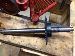
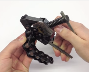
I ordered the large sprockets directly from Martin Sprocket. They came with a 1/2 inch bore and no key or set screw. The MDM truck kit came with 1/2 inch axle stock, but I prefer 3/4 inch and substituted using 3/4 inch round CRS. The sprockets were drilled and bored from 1/2 inch to 3/4 inch, then placed on the axles in the correct location and taper drilled all the way through. The sprocket was locked into place by driving the taper pin and cutting off the excess.
I later found the equivalent sprocket from McMaster-Carr. The next wheel-sets I build will use the McMaster-Carr sprocket, as it is already bored for a 3/4 inch axle and includes a 1/8 inch keyway and set screw. It is the same price as the Martin sprocket (I'm guessing the McMaster-Carr sprocket is also made by Martin).
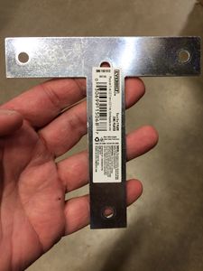
T Plate 5x5 inches, unmodified
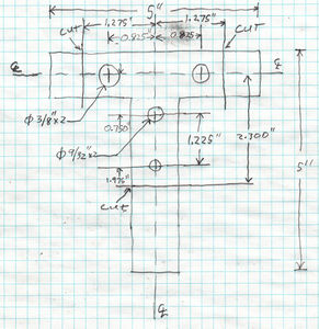
5x5 inch T Plate modifications
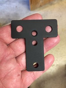
Here is a Tee Brace after drilling the extra holes, trimming the arms and painting.
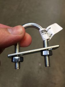
Everbuilt #304 1/2 inch pipe U-bolt
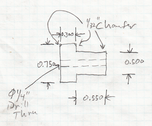
Motor mount bushing
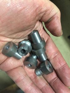
A handful of newly turned motor mount bushings. A total of 16 bushings were required.


Assembly
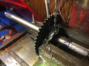
Drilling a hole through the sprocket and axle. The hole will be tapered with a reamer. Be sure to use lots of lubricant to keep the bit cool. Make sure the hub of the sprocket is facing towards the short end of the axle.
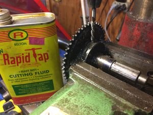
Reaming a tapered hole after drilling. Rapid Tap works well to keep the reamer cool. Pull the reamer out frequently to extract chips, then apply more cutting fluid.
A completed axle with the #25 chain drive sprocket attached with a tapered pin. The pin has been lightly driven in with a chisel and hammer, and the extra length cut off neatly.
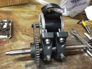
The pillow blocks are slid onto the axles. Make sure both Zerk fittings point the same way. Assemble the motor onto the pillow bearing using the motor mount bushings and a bolt, both inserted from the underside of the pillow block towards the motor.
Assembling the #25 chain on the sprocket and motor. This step is performed after attaching the motor to the pillow blocks using four motor mount bushings and four M6-1.00 x 40 hex cap bolts.
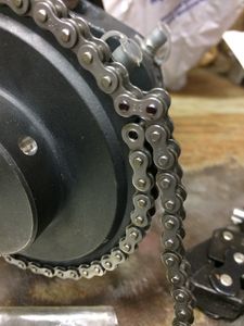
Place the chain on the two sprockets in order to measure the correct length. You will need to use either a Connecting Link or Offset Link, depending on which section of the chain must be removed. Use a black Sharpie marker to indicate which link pins to remove.
Use a Chain Breaker to remove the unwanted link. Refer to the video Splitting a Chain with a Chain Breaker
The chain is attached with a Connecting Link in this case.
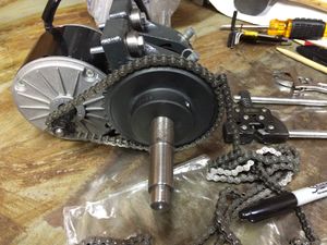
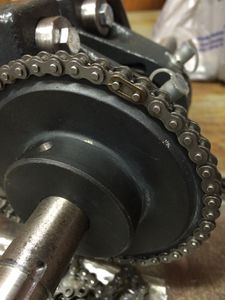
A completed drive chain, waiting for wheels to be pressed on. Note that the Zerk fittings on the bearings are both on the same side.
Washers may be inserted between the motor and pillow block to remove slack in the chain.
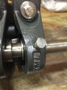
The Zerk fittings on the pillow block were protected by a plastic cap. The Zerk is unscrewed in order to remove the cap. Be sure to tighten the Zerk fitting back in place.
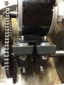
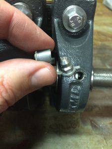
These pillow blocks were selected because they include set screws that prevent the blocks from sliding laterally on the axle. This photo shows one of the set screws. Make sure the chain is aligned between the motor sprocket and the axle sprocket, then tighten the Allen set screws on both bearings. Note that there are two set screws per bearing. Also note that the set screws are on the opposite side from the sprockets.
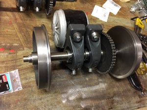
A completed wheelset after pressing on the wheels. The wheelset is ready to be mounted into the truck frame.
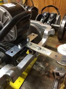
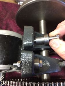
Test fitting the T-brace along with the U-bolt before cutting the extra length off the T-brace. The motor T-brace is attached to the motor pillow block using two nylon lock nuts. Likewise the U-bolt nuts are replaced with nylon lock nuts. This allows the tension on the rubber hose to be adjusted. The U-bolt/rubber tube configuration allows the motor to rotate on the axis as the wheelset moves up and down over the road.
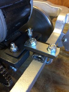
The motor is secured to the outside frame using the modified Tee brace along with the UBolt and a section of rubber tubing. The combination allows the motor to move up and down with the shifting height of the axle. The flat bracket supplied with the UBolt is added on top of the Tee brace for added strength.


Wiring
The factory connectors were cut off from the feed wires to the motor. Standard fork terminals were crimped onto the ends of the wires.
Note that the motors are facing opposite directions (see Photo 1). This will require swapping the leads on one of the motors so that the wheels will turn in the same direction.
External Links
- AAR Type A Switcher Truck
- AAR Type A Truck, Archive.org
- "Railway Cab Truck", U.S. Patent 2,137,704
- "Installation and Maintenance of Roller Chains" (PDF)
- "Splitting a Chain with a Chain Breaker", YouTube.com
- Alco S-4 Truck Motors, Chaski.org
- Powerpole Connectors, Anderson Power Products
- PWRcrimp Crimp Tools, West Mountain Radio