Baker valve gear: Difference between revisions
Jump to navigation
Jump to search
No edit summary |
|||
| Line 2: | Line 2: | ||
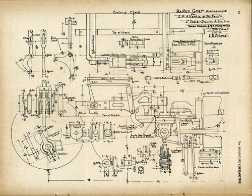
[[File:The miniature locomotive mayjun1953 016 BakerGearDrawing.jpg|thumb|center|500px|Baker valve gear drawing for 1-inch scale SP Atlantic by [[Lester Friend|Lester D. Friend]], from "[[The Miniature Locomotive]]", May-June 1953.]] | [[File:The miniature locomotive mayjun1953 016 BakerGearDrawing.jpg|thumb|center|500px|Baker valve gear drawing for 1-inch scale SP Atlantic by [[Lester Friend|Lester D. Friend]], from "[[The Miniature Locomotive]]", May-June 1953.]] | ||
== Setting == | |||
Rules for Timing Locomotives with Baker Gear | |||
From [[Friends Models|Friends Steam Models Catalog 5A]]: | |||
# Block up wheels in running position. | |||
# Get front and back dead-centers on crosshead and mark these positions on crosshead and mark these positions on crosshead guide with a fine scratch line. (This measurement should be obtained by turning the drive wheels by hand. Always turn them in the same direction.) | |||
# make two "dummy" pins, one for the gear connecting rod lower pin hole and one for the eccentric crank pin hole, these pins to have small No. 60 drill hole in the center for dividers. | |||
# Set the gear connecting rod in mid position, so that the reverse yoke swings back and forth without moving the bell-crank. | |||
# Use a pair of accurate dividers: set the position on front dead-center (by turning the drive wheels). Measure from the center of the pin in the gear connecting rod to the center of the pin in the eccentric crank. Repeat the operation with the piston on the back dead-center. Move the eccentric crank until both show the same measurements. | |||
# To check the measurement of the eccentric rod, set the crosshead on front dead-center. Move the reverse yoke back and forth; the valve should not move. The same holds true for the back dead-center. | |||
# Now set the valve on the valve rod adjustment to have equal "leads" on front and back dead-centers, when the reverse yoke is in mid-gear. | |||
# Precision cannot be over emphasized in timing a locomotive. | |||
== References == | == References == | ||
Revision as of 00:01, 6 December 2017

Baker valve gear drawing for 1-inch scale SP Atlantic by Lester D. Friend, from "The Miniature Locomotive", May-June 1953.
Setting
Rules for Timing Locomotives with Baker Gear
From Friends Steam Models Catalog 5A:
- Block up wheels in running position.
- Get front and back dead-centers on crosshead and mark these positions on crosshead and mark these positions on crosshead guide with a fine scratch line. (This measurement should be obtained by turning the drive wheels by hand. Always turn them in the same direction.)
- make two "dummy" pins, one for the gear connecting rod lower pin hole and one for the eccentric crank pin hole, these pins to have small No. 60 drill hole in the center for dividers.
- Set the gear connecting rod in mid position, so that the reverse yoke swings back and forth without moving the bell-crank.
- Use a pair of accurate dividers: set the position on front dead-center (by turning the drive wheels). Measure from the center of the pin in the gear connecting rod to the center of the pin in the eccentric crank. Repeat the operation with the piston on the back dead-center. Move the eccentric crank until both show the same measurements.
- To check the measurement of the eccentric rod, set the crosshead on front dead-center. Move the reverse yoke back and forth; the valve should not move. The same holds true for the back dead-center.
- Now set the valve on the valve rod adjustment to have equal "leads" on front and back dead-centers, when the reverse yoke is in mid-gear.
- Precision cannot be over emphasized in timing a locomotive.