Air brakes: Difference between revisions
| Line 17: | Line 17: | ||
=== Pull to Apply === | === Pull to Apply === | ||
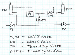
[[File:AirBrakes PullToApply Diagram.jpg|thumb|right|300px|Schematic of Automatic Air Brakes, Pull to Apply type.]] | [[File:AirBrakes PullToApply Diagram.jpg|thumb|right|300px|Schematic of Automatic Air Brakes, Pull to Apply type. R1 is an air reservoir.]] | ||
The ''Pull to Apply'' style brakes are so called because the dual acting cylinder is setup to apply braking pressure by pulling on the control rod. [https://web.archive.org/web/20080705223401/http://livesteaming.com/Air%20brakes.htm According to Harry Haas], the Pull to Apply Automatic Air Brake was designed by [[Jim Murray]]. Harry describes the system as follows: | The ''Pull to Apply'' style brakes are so called because the dual acting cylinder is setup to apply braking pressure by pulling on the control rod. [https://web.archive.org/web/20080705223401/http://livesteaming.com/Air%20brakes.htm According to Harry Haas], the Pull to Apply Automatic Air Brake was designed by [[Jim Murray]]. Harry describes the system as follows: | ||
Revision as of 23:24, 3 July 2015
Straight Air

Perhaps the simplest form of air brakes is referred to as "straight air brakes". This configuration uses single acting cylinders. No air pressure is present in the brake system while the brakes are release. Air pressure is added to the system to apply the brakes. No air tanks are required for straight air brakes.
Balanced
Balanced air brakes rely on dual-acting cylinders to apply and release the brakes. A single air line from the locomotive brake valve controls the operation of the brakes.
Balanced air brakes are also referred to as "Automatic Air Brakes", because a break in the air line (i.e. part of the train becomes uncouple and pulls the glad hands apart) will cause all brakes to apply on both segments of the train. This operation is in accordance with prototype air brake systems.
Pull to Apply
The Pull to Apply style brakes are so called because the dual acting cylinder is setup to apply braking pressure by pulling on the control rod. According to Harry Haas, the Pull to Apply Automatic Air Brake was designed by Jim Murray. Harry describes the system as follows:
- The AAB circuit is designed to operate at 40 PSI. The air cylinders used have a bore of 1-1/16 inch. The bore depends on the type mechanical setup used on the trucks.
- The air reservoir for each car should be as large as possible. I use 2 inch by 10 inch PVC pipe (schedule 40).
- The control system is from the locomotive cab. A plunger type air pressure regulator (Clippard MAR-1C) under the cab, activated by a cam setup with an air brake stand above the floor. One for the independent air or steam brakes on the locomotive (engine and tender) and one for the automatic air brakes on the train.
- The air switch (Clippard TV-3S) allows the brakes on each car to be individually released without voiding all the air in the reservoir (e.g. to take the car out of the system and remain within the train). Also, a car may be set out on a siding and the brakes released.
Bill Donovan explains how the system works:
- In the system where the train line is directly connected to the non-rod end of the cylinder similar pressures will cause the rod to extend when the brakes are released. This is due to the fact that the area of the piston on the rod side is reduced by the area of the rod so at the same pressure less force is applied to the rod side than to the non-rod side. If your configuration of the brake rigging works with the rod extended to release the brakes this is correct.
- In an ideal configuration the diameter of the brake cylinder and the brake ratio would be selected based on the weight of the car such that all cars in the train responded to the same pressure reductions in a similar way. In an emergency this would provide maximum braking that can be applied considering the effect on the passengers and wheel slip.
Push to Apply
Clippard Parts
Serveral current air brake designs use Clippard parts. They have been reported to work well, are virtually leak free, and Clippard's website is easy to navigate. Here is a list of commonly used parts.
- SDR-17-1 : Stainless steel double-acting cylinder, 1 inch stroke, 1-1/16 inch bore, 5/16 inch shaft
- MAR-1C : Plunger-type pressure regulator, 10-100 PSI
- CT4 : #10-32 to 1/8” ID Hose Connector, designed for Clippard's Polyurethane hose
- T44-4 : Tee fitting, 1/8 inch ID
- URH1-0804-BKS : Urethane tube 1/8 inch ID
- 11924-1-ENP : 1/8 inch Pipe to 1/8 inch hose fitting
- TV-3SP : 3-Way Toggle Valve, ENP Steel Toggle, 1/8" NPT
- MCV-2 : Check Valve, #10-32 Ports
Non-equalized
External References
- Gerry Stuteville's "Auto Air Brakes"
- "Affordable Air Brakes by Harry Haas"
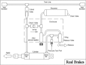
- "Real Brakes for Model Railroaders"
- "Air brake question", Chaski.org
- "Air brakes", Chaski.org
- "Freight Car Brake Rigging Arrangements", Wabtec Corp (PDF)
- "Wabtec Freight Catalog" (PDF)
- Mountain Car Company Air Brakes
- Tom Bee Straight Air Brakes
- "Air Brakes for 7.5 Inch Cars", Rick White
- Steam Locomotive Air Brakes
- Bettendorf freight truck with brake rigging, Railroad Warehouse
- "Building an External Air Compressor"

